The top video demonstrates the setting of time values on the controller, and the trigger button. The green LED is lit when the controller is free to begin a new sequence, the red LED is lit when the controller is busy.
The lower video shows the controller in use. The shutter can be heard opening. Two clicks follow from the solenoid valve opening and closing twice (my valve is only audible on closing), the flash fires, and the shutter closes.
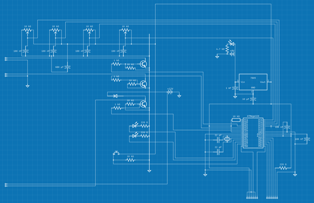
Here is my schematic drawn using circuit-diagram.org . My Arduino code follows.
I plan to include a detailed guide on soldering and assembling the circuit in the future.
#include <LiquidCrystal.h>
LiquidCrystal lcd(8, 9, 10, 11, 12, 13);

int potpin1 = A2; // drop 1 size
int potpin2 = A3; // drop 2 size
int potpin3 = A4; // delay between first and second drop
int potpin4 = A5; // delay between second drop and flash
int campin = 4;
int flashpin = 3;
int trig = 7; // button to open shutter and start sequence
int valvepin = 2;

int red = 6;
int green = 5;

int p1;
int p2;
int p3;
int p4;


int t1;// time to keep valve open 1
int t2;// time to keep valve open 2
int t3;// delay between first and second drop
int t4;// delay between second drop and flash

int t1min = 20 ;// minimum valve open time 1
int t2min = 20 ;// minimum valve open time 2
int t3min = 0 ;// minimum delay between first and second drop
int t4min = 300 ;// minimum delay between second drop and flash

int t1max = 800 ;// maximum valve open time 1
int t2max = 800 ;// maximum valve open time 2
int t3max = 800 ;// maximum delay between first and second drop
int t4max = 1300 ;// maximum delay between second drop and flash


void setup() {
  Serial.begin(9600);
  lcd.begin(16, 2);

  analogReference(EXTERNAL);

  pinMode (valvepin, OUTPUT);
  pinMode (campin, OUTPUT);
  pinMode (flashpin, OUTPUT);
  pinMode (trig, INPUT);

  pinMode (red, OUTPUT);
  pinMode (green, OUTPUT);

  digitalWrite(valvepin, LOW);
  digitalWrite(campin, LOW);
  digitalWrite(flashpin, LOW);

  digitalWrite(red, LOW);
  digitalWrite(green, LOW);
}

void loop() {
  if (digitalRead (trig)== LOW){
    digitalWrite(red, HIGH);
    digitalWrite(green, LOW);

    lcd.clear();

    p1 = analogRead (potpin1);
    p2 = analogRead (potpin2);
    p3 = analogRead (potpin3);
    p4 = analogRead (potpin4);

    t1 = map(p1,0,1023,t1min,t1max);
    t2 = map(p2,0,1023,t2min,t2max);
    t3 = map(p3,0,1023,t3min,t3max);
    t4 = map(p4,0,1023,t4min,t4max);


    Serial.println (t1);
    Serial.println (" ");
    Serial.println (t2);
    Serial.println (" ");
    Serial.println (t3);
    Serial.println (" ");
    Serial.println (t4);

    lcd.print(t1);
    lcd.print(" ");
    lcd.print(t2);
    lcd.print(" ");
    lcd.print(t3);
    lcd.print(" ");
    lcd.print(t4);
    delay (210);

  }

  if (digitalRead (trig)== HIGH){
    digitalWrite(red, LOW);
    digitalWrite(green, HIGH);


    p1 = analogRead (potpin1);
    p2 = analogRead (potpin2);
    p3 = analogRead (potpin3);
    p4 = analogRead (potpin4);

    t1 = map(p1,0,1023,t1min,t1max);
    t2 = map(p2,0,1023,t2min,t2max);
    t3 = map(p3,0,1023,t3min,t3max);
    t4 = map(p4,0,1023,t4min,t4max);;


    digitalWrite (campin,HIGH); // open shutter
    delay (500);
    digitalWrite (campin,LOW);


    digitalWrite (valvepin,HIGH); // start first drop
    delay (t1);
    digitalWrite (valvepin,LOW); // end first drop

    delay (t3); // delay between drops

    digitalWrite (valvepin,HIGH); // start second drop
    delay (t2);
    digitalWrite (valvepin,LOW); // end second drop

    delay (t4);

    digitalWrite (flashpin,HIGH); // trigger flash
    delay (500);
    digitalWrite (flashpin,LOW);


  }

}